

Introduction
An access control wiring diagram shows how every device on a controlled door connects back to the door controller: the reader, the electric lock, the exit button, the door contact and the power supply. Get the wiring right and the door behaves predictably every day, during a power cut and when the fire alarm sounds. This guide walks through each connection in plain language.
In short: the reader and door inputs go to the controller, the lock is powered from its own supply and switched through the controller’s relay, and the fire alarm and emergency release sit in the lock power circuit.
The parts on an access-controlled door
Before drawing any wiring diagram, list what the door needs. A typical single door has six parts:
- Door controller: the panel that stores users and rules and makes the open or deny decision. Browse our door controllers for one-, two- and four-door options.
- Reader: card, PIN, fingerprint or face reader on the outside of the door. See our fingerprint access control and face recognition terminals ranges.
- Electric lock: magnetic lock (maglock), electric strike, electric bolt or motor lock.
- Exit button: a request-to-exit (REX) push button or touchless sensor on the inside.
- Door contact: a magnetic sensor that reports whether the door is really closed.
- Power supply: a dedicated access control power supply, ideally with battery backup.
On escape-route doors you will also see a fire alarm interface and usually a green emergency break-glass unit beside the door.
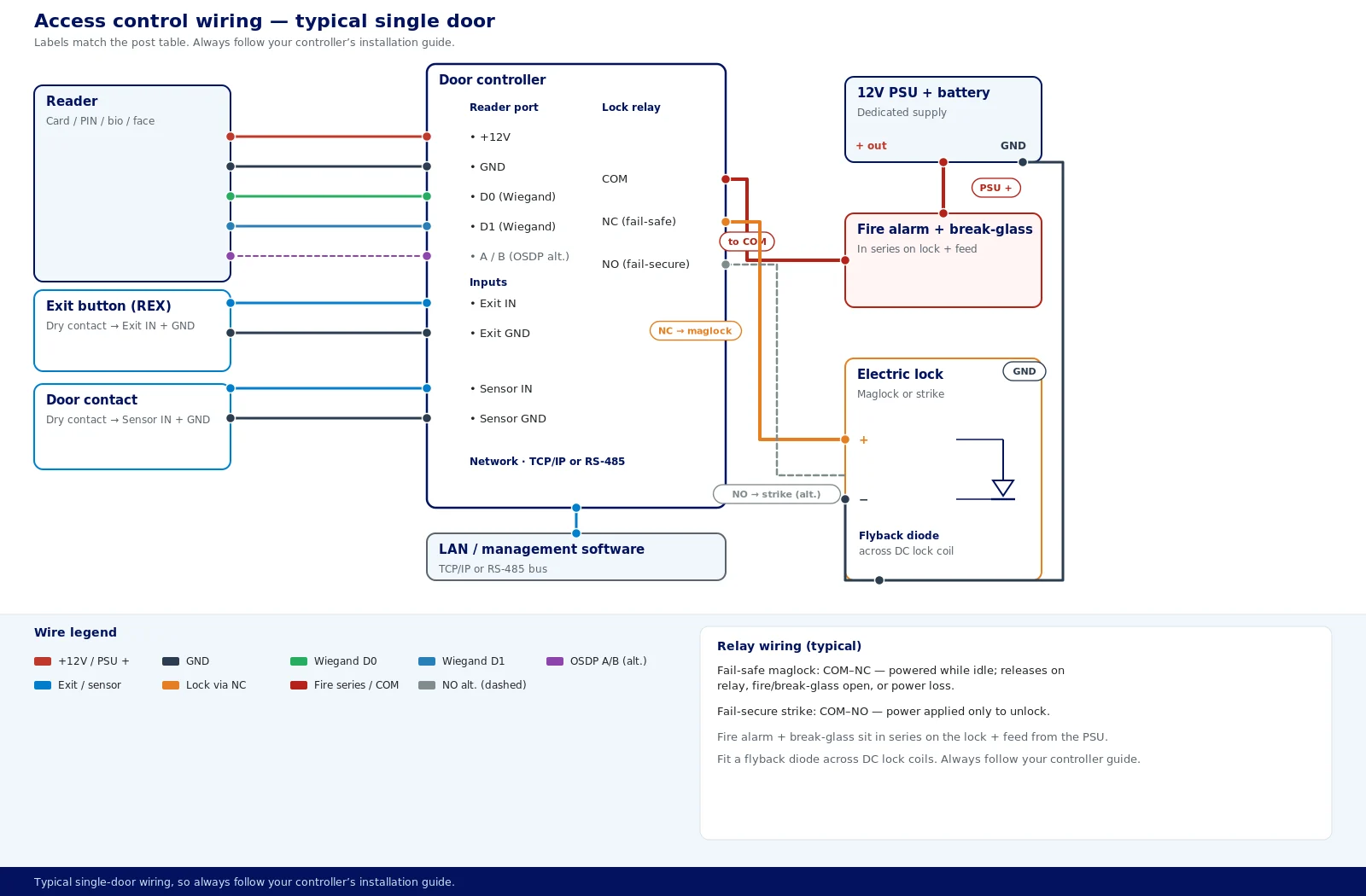
Access control wiring diagram: connection by connection
Terminal names differ between manufacturers, so always follow the wiring diagram in your controller’s installation guide. The logic below applies to almost every door.
| Device | Connects to | Typical conductors |
|---|---|---|
| Wiegand reader | Reader port | +12V, GND, D0, D1, LED, beeper |
| OSDP reader | RS-485 port | +12V, GND, A, B |
| Exit button | Exit input | Input and GND |
| Door contact | Sensor input | Input and GND |
| Fail-safe lock | Lock relay | COM and NC |
| Fail-secure lock | Lock relay | COM and NO |
| Controller | Network | TCP/IP or RS-485 |
1. Power
Feed the controller and the locks from a dedicated access control power supply rather than from the controller’s own outputs where lock current is high. Add up the current drawn by the controller, readers and locks and choose a supply with spare capacity and battery backup.
2. Reader
Run the reader cable from the outside of the door back to the controller on the secure side. A Wiegand reader normally uses data lines D0 and D1 plus power and optional LED and beeper control. An OSDP reader uses power plus a two-wire RS-485 data pair.
3. Lock
The lock’s positive feed from the power supply passes through the controller’s lock relay. For a fail-safe maglock it is usually wired through COM and NC, so the lock is powered while idle and releases when the relay operates. For a fail-secure strike it is wired through COM and NO, so power is applied only to unlock.
4. Exit button and door contact
A standard push-to-exit button is a dry contact: wire its normally open contact between the controller’s exit input and ground. The door contact goes to the sensor input in the same way, which lets the controller raise door-forced and door-held-open alarms.
5. Fire alarm and emergency release
On escape routes, a fire alarm relay and an emergency break-glass unit are placed in the lock power circuit so either one cuts power and releases fail-safe locks, independent of the controller.
6. Network
Networked panels such as the ZKTeco C3 series connect to the LAN over TCP/IP, and management software such as ZKAccess 3.5 then sets users, doors and time zones for every door.
Fail-safe vs fail-secure locks
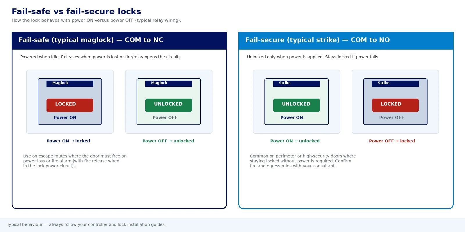
The lock type decides how the door behaves when power is lost, so choose it before you wire anything.
| Factor | Fail-safe | Fail-secure |
|---|---|---|
| Power lost | Unlocks | Stays locked |
| Typical lock | Maglock | Electric strike |
| Relay contact | COM and NC | COM and NO |
| Escape routes | Normally used | Needs free mechanical exit |
| Best for | Main and fire-exit doors | Stores, server rooms |
Many strikes and bolts can be set to either mode, so confirm the setting on site. Whatever the lock, fit suppression (a diode or the suppressor supplied with the lock) across the coil to protect the controller’s relay contacts.
Wiegand vs OSDP reader wiring
The reader interface changes the cable, the distance and the security of the link.
| Factor | Wiegand | OSDP |
|---|---|---|
| Data direction | One-way | Two-way |
| Reader supervision | No | Yes |
| Encryption | No | Secure Channel |
| Data wires | D0 and D1 | RS-485 pair |
| Typical maximum run | About 150 m | About 1,200 m |
| Readers per cable | One | Several (multi-drop) |
Wiegand remains common because so many readers support it. For new projects, OSDP is the stronger choice where the controller supports it; the ZKTeco C3 Pro Plus accepts both OSDP and Wiegand readers.
How controller types change the wiring
Standalone reader-controllers
A standalone unit combines reader and controller in one device at the door, so the lock and exit button wire straight to it. It is simple for one door, but the decision is made on the exposed side of the door.
Multi-door panels
A networked panel on the secure side serves several doors, with every reader, lock and input cabled back to one enclosure. The ZKTeco C3-100, C3-200 and C3-400 and the inBIO160, 260 and 460 come in one-, two- and four-door versions, so plan cable routes around where the panel will sit.
Biometric controllers
With a biometric controller such as the inBIO series, fingerprint templates are held in the panel and ZKTeco slave readers at the door only capture the finger. The inBIO supports TCP/IP and RS485 communication.
IP and PoE devices
IP controllers and terminals run over the building network. Where a device is powered over Ethernet, locks usually still need their own supply, because lock current can exceed what a PoE port provides.
Checklist: choosing a controller for your wiring plan
- Doors and layout: how many doors, and how far is each from a sensible panel position?
- Reader interface: does the panel accept the readers you want: Wiegand, OSDP or the manufacturer’s own readers?
- Lock type: fail-safe or fail-secure on each door, and is the relay suitable for the lock?
- Inputs: an exit input and door contact input for every door, plus any alarm inputs.
- Power: lock current, cable length and battery backup time you need.
- Fire interface: how the fire alarm signal releases each escape-route door.
- Network and software: TCP/IP or RS-485, and which software will manage users and reports.
- Growth: spare door, user and event capacity, checked against the datasheet.
If you are comparing panels, our door controllers page lists the ZKTeco controllers we supply and install.
Wiring basics and good practice
- Keep the controller on the secure side. Mount it in a locked cabinet, ceiling void or comms room, never next to the outside reader.
- Use the right cable. Shielded multi-core for Wiegand readers, twisted pair for RS-485 and OSDP, Cat6 for TCP/IP, and a lock cable heavy enough to limit voltage drop over the run.
- Earth shields at one end. Connect cable shields at the controller end only to avoid earth loops.
- Separate from mains. Route low-voltage access cabling away from mains power cables.
- Label everything. Mark each cable at both ends with the door and device it serves.
- Test every door. Before handover, check a valid credential, an invalid one, the exit button, door forced, door held open, power failure and fire release.
Access control wiring in the UAE
Villas
Villa main doors and gates are often far from the house electrics, so cable length and voltage drop matter. Outdoor gates need readers built for heat, dust and sun, such as the Suprema BioEntry W2 or Suprema BioLite N2.
Offices and free zones
In shared office buildings and free-zone units, agree cable routes, ceiling access and the fire alarm interface point with building management before installation. Placing a multi-door panel centrally keeps reader runs short and leaves room for the tenant to add doors later.
Heat and cabinets
Keep controllers and power supplies in conditioned indoor spaces or ventilated cabinets rather than in hot plant rooms or exposed outdoor boxes, as heat shortens battery and electronics life.
Fire alarm release
Access-controlled doors on escape routes are normally required to release on a fire alarm signal. Your consultant and the Civil Defence approval set the exact requirement for your building, so plan the interface at design stage.
Time attendance
Many UAE businesses use the same device for doors and attendance. Terminals such as the ZKTeco SpeedFace-V5L handle both, which saves cabling a second set of devices.
Access control wiring FAQs
How do you wire a maglock to an access controller?
Power the maglock from a dedicated access control power supply and pass its positive feed through the controller’s lock relay, usually COM and NC, so it is powered while idle and releases when the relay operates. Place the fire alarm release and break-glass unit in the same circuit.
Which relay terminals are used for fail-safe and fail-secure locks?
Fail-safe locks such as maglocks are usually wired through COM and NC, so they release when the relay operates or power is lost. Fail-secure locks such as many electric strikes are wired through COM and NO, so power is applied only to unlock.
How many wires does an access control reader need?
A Wiegand reader typically uses six conductors: power, ground, D0, D1, LED and beeper, although some need only four. An OSDP reader uses four: power and ground plus a two-wire RS-485 data pair.
How far can a reader be from the controller?
Wiegand reader runs are typically limited to around 150 metres with shielded cable, while OSDP over RS-485 can run to around 1,200 metres. Always check the limits in the reader and controller datasheets for your exact models.
Does an exit button need its own power?
A standard push-to-exit button is a dry contact wired between the controller’s exit input and ground, so it needs no power. Touchless and infrared exit sensors do need a power feed, usually from the access control supply.
Should access-controlled doors release on a fire alarm?
Doors on escape routes are normally wired to release automatically when the fire alarm activates, usually using fail-safe locks. The exact requirement for your building is set by your consultant and the Civil Defence approval.
Plan your door access wiring with us
Talk to the eTOP access control team. Send us your door schedule or a drawing and we will come back with a specification, wiring approach, datasheets and a written price, normally within 24 hours. Our own engineers survey, install, commission and maintain access control across all seven emirates.
- Dubai:+971 4 455 9007
- Abu Dhabi:+971 2 650 3433
- Email:sales@etopme.ae
Ready to choose hardware? See our door controllers, then request a quotation or read more about our team.